
A null-modem cable connects two RS-232 DTE devices directly. It crosses the transmit and receive signals so that each device’s output reaches the other device’s input. A straight-through cable connects matching pin numbers and may not work for a direct connection between two DTE devices.
A DB9 null-modem cable can use a basic three-wire connection or include additional wires for hardware flow control. Check the documentation for both devices before choosing a wiring arrangement.
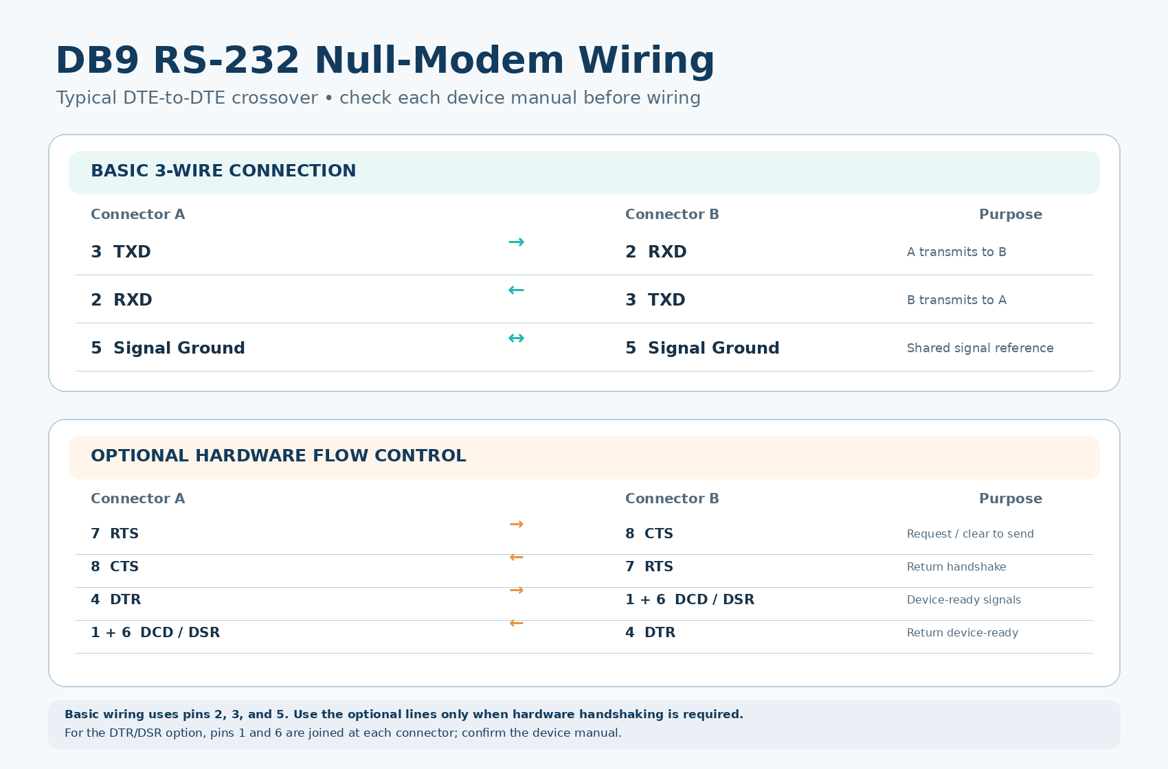
The diagram below shows common DB9 null-modem connections.
Basic three-wire connection
For basic serial communication without hardware flow control, connect:
• Pin 2 on one end to pin 3 on the other
• Pin 3 on one end to pin 2 on the other
• Pin 5 to pin 5 for signal ground
Pins 2 and 3 carry receive and transmit data on a typical DB9 DTE port. Crossing them connects each device’s transmit signal to the other device’s receive signal.
Full hardware flow-control connection
If both devices use RTS/CTS hardware flow control, those signals also need to cross:
• Pin 7 to pin 8
• Pin 8 to pin 7
Some full-handshake cable designs also connect the readiness signals:
• Pin 4 on one end to pins 1 and 6 on the other
• Pins 1 and 6 on the first end to pin 4 on the other
• Pin 5 to pin 5
Pin 9 is not connected in this wiring example. Handshake wiring varies, so follow the cable pinout specified by the equipment manufacturer.
Before making or buying a cable
Confirm that both ports use RS-232 and identify whether each device is DTE or DCE. Check the connector pinout and the required flow-control method. A cable’s connector gender alone does not tell you whether it is straight-through or null-modem.
When building a cable, verify the pin numbers from the connector’s markings or the manufacturer’s drawing. The view from the mating side can appear reversed compared with the solder side. With both devices disconnected, use a continuity tester to check each connection and make sure there are no shorts between pins.
Troubleshooting a connection
If communication fails, confirm that the cable wiring matches both device manuals. Then check that both devices use the same baud rate, data bits, parity, stop bits, and flow-control setting. A cable wired for hardware flow control may not work as expected when the devices are configured for no flow control, or the reverse.
If you need to connect a computer’s USB port to an RS-232 device, explore our USB-to-RS232 adapters. The adapter provides an RS-232 interface; the cable wiring still needs to match the device connection.
Technical references
• Analog Devices: Asynchronous Serial-to-Ethernet Device Servers
• Microsoft Learn: Null-Modem Cable Wiring